One of the famous issue you'll encounter when designing and printing technical parts with a 3d printer is the small difference between the dimension of your designed holes and the physical part. This is due to the lack of so called arc compensation.
The great NopHead made a point in figuring out precisely why we suffer from this error and shared his finding in a blog post where he introduces polyholes. They are basically polygons approximations of round holes which, once printed, will allow to fit a given diameter.
Skeinforge way of fixing hole size
Enrique Perez, author from skeinforge, one of the first usable reprap slicer, designed a solution to get better shape hole through the use of his stretch plugin.
In the chain of manipulation which makes skeinforge outputs some GCode out of a STL model, there is an optionnal step where points being part of a perimeter are moved away from the center of the hole they border.
Due to this, the nozzle position and extrusion volume are nearer of the theorical position mathematically described in the arc compensation article.
This is nice and good, but the reprap community slicer needs are moving fast and skeinforge in itself isn't actively developped anymore. It could be time to try to reuse this technic and apply it to the current slicers.
Adapting the stretch plugin
One of the good thing with Enrique code is that it's a GCode filter. It takes GCode and provide GCode too so we can hook up our solution after a slicer has generated proper GCode.
After having extracted the stretch plugin from skeinforge code and making sure that licenses are fine (it's Affero GPL and is integrated into GPLv2+ code; which I might have to switch to GPLv3), I jut made sure that I have a nice regression test to ensure that the behaviour would remain during refactoring.
A long work of simplification (for removing skeinforge specific which weren't useful anymore) and understanding for adaptation to other slicer ensues.
At this point of the chain where the skeinforge plugin was ran, all loops were flagged (inner vs outer, external vs internal perimeters), no extrusion were generated yet and stop and start of extrusion where flagged with M101 and M103 GCode opcodes in a systematic way. All of this had to be taken into account to be a tad more flexible.
The result is that with a patched version of slic3r (I opened an issue to integrate this into the main branch) and a few selected settings (namely "relative extrusion", "outer perimeter first" and "verbose GCode generation"), you can generate GCode which is accepted by my gcodeutils set of filters.
Preliminary results
I picked openscad to create a small model with a 8mm and 6mm holes (which you don't go normally to generate holes able to fit a 8mm or 6mm rod) and asked slic3r to generate GCode for it.
Out of this code, I then printed it and variations based on various strength and algorithm of stretch compensation.
Here is the result :
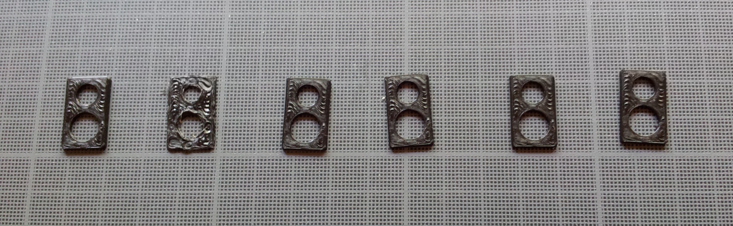
Leftmost is the original one, where the 8mm hole is about 7.82mm at its widest.
Second to left is a failure as my Z was reset to 0 middle print. My bad, I did a mistake in the code and weren't near to the printer when printing this (newborn caring can be quite time consuming :)
Rightmost is the most agressive version, same settings as those commited on GitHub at the moment (d60be485) and its 8mm hole is 8.01mm width at most.
All of this, of course, without changing the outer size (which remained at 11.96 +/- 0.02mm and 19.98 +/- 0.02mm during all those experiments).
I still have some documentation to write, some code to add to allow for command line configuration. But you can expect a quick release with this GCode stretcher filter. The algorithm will probably requires tweaking so I still wouldn't recommend it for general use until some feedback from beta testers has been factored into the code.
Happy printing !